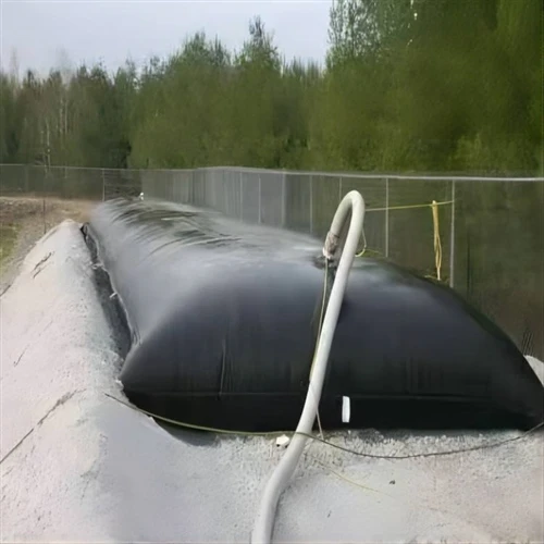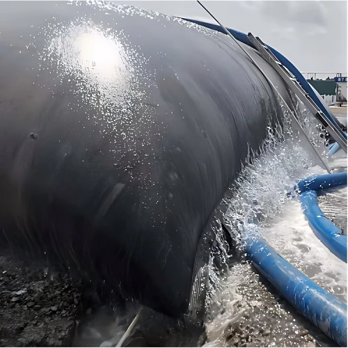
Dewatering filter bags, also called geotextile dewatering bags or geotextile tubes, are used to separate water from dredged sediment, wastewater sludge, industrial sludge, mining slurry and other high-water-content materials.
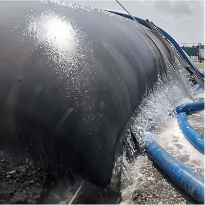
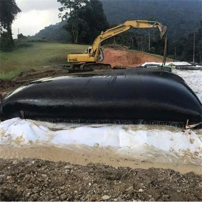
The basic process is straightforward: the sludge or slurry is pumped into a specially woven polypropylene geotextile tube. The geotextile acts as a filtration layer. Water passes through the fabric under hydraulic pressure and gravity, while most of the solid particles remain inside the tube. After repeated filling and drainage cycles, the material inside the tube becomes more concentrated and consolidated.
For dredging and sludge treatment projects, the important questions are not simply whether a dewatering bag can remove water. The actual design depends on sludge type, solids concentration, particle size, polymer selection, filling rate, bag dimensions, drainage area, filtrate collection and final disposal requirements.
What Is a Dewatering Filter Bag?
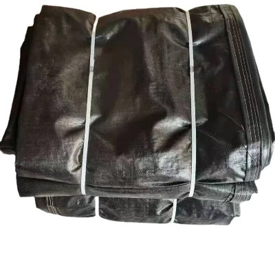
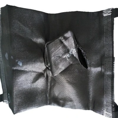
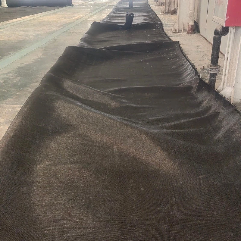
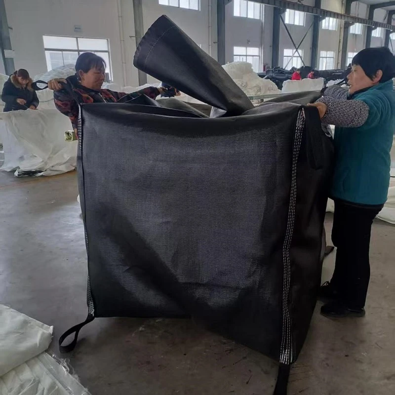
A dewatering filter bag is a large tubular container manufactured from high-strength woven geotextile.
The fabric is engineered with a filtration structure and an equivalent pore size that allows water to pass through while retaining a large proportion of suspended and solid particles.
The tube can be manufactured in different diameters and lengths according to the project. For large projects, multiple tubes can be installed in the same drainage area, and the number of tubes can be increased according to the required treatment capacity and available site area.
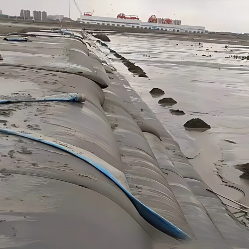
The same basic technology can also be adapted for applications where the tube is filled with sand, mortar or other specified materials, such as coastal protection, breakwaters, seawalls and cofferdam-related works.
| Parameter | Common Industry Reference |
|---|---|
| Main material | Woven polypropylene (PP) geotextile |
| Yarn type | Flat yarn, round yarn, slit-film yarn, monofilament or combined yarn structures |
| Fabric structure | Woven filtration structure |
| Typical fabric mass | Approximately 200–1,200 g/m², depending on application and loading requirements |
| Apparent opening size (AOS) | Commonly selected in the approximate range of 0.05–0.30 mm, subject to sediment characteristics |
| Tube diameter | Common project range: approximately 2–30 m |
| Tube length | Commonly customized from several meters to more than 50 m |
| Seam configuration | Factory-sewn seams designed according to tube size and filling load |
| Filling material | Dredged sediment, municipal sludge, industrial sludge, mining slurry, sand, mortar or specified slurry |
| Filling method | Dredger, suction pump or sludge pump |
| Conditioning | Polymer/flocculant when required |
| Filtration mechanism | Geotextile filtration + hydraulic pressure + gravity drainage |
| Drainage method | Gravity drainage |
| Solid retention | More than 99% can be achieved under suitable material and operating conditions |
| Reference volume reduction | More than 90% may be achieved under suitable conditions |
| Filling pressure | Project-specific; controlled according to tube design and filling condition |
| Drainage area | Determined according to tube quantity, tube size and site conditions |
| Final handling | Reuse, reclamation, construction application or regulated disposal, depending on material testing |
These are industry reference values rather than fixed specifications. Actual fabric weight, AOS, tensile strength, seam strength, tube diameter and length should be selected according to the sludge characteristics and project design.
How Does a Dewatering Filter Bag Work?
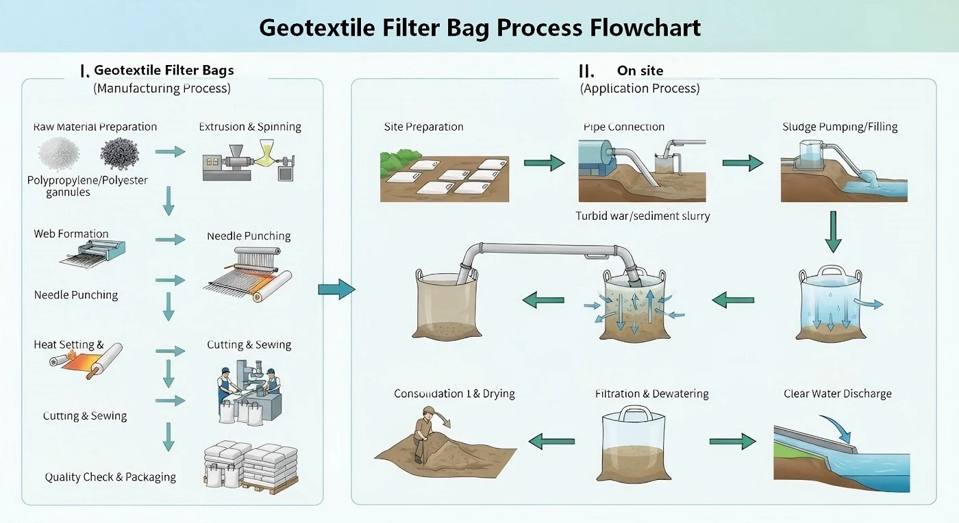
The dewatering process can be understood through four basic stages.
Step 1 - Sludge Extraction
Dredged sediment or sludge is first extracted using a dredger, suction pump or sludge pump.
For river and lake dredging, the material may contain a large amount of water and fine suspended particles. Direct mechanical handling is difficult when the solids concentration is low.
The material is therefore transported through a pipeline to the treatment area.
Step 2 - Polymer Conditioning and Flocculation
Before entering the dewatering tube, a suitable flocculant or polymer may be added.
The purpose is to change the physical condition of the suspended particles.
Small particles normally remain dispersed in water and are difficult to retain efficiently through filtration. After polymer conditioning, particles aggregate into larger structures known as flocs.
The flocculation process can be described as:
Fine suspended particles → Polymer conditioning → Particle aggregation → Larger flocs → Improved solid-water separation
The polymer dosage cannot be selected only by using a fixed number. It should normally be determined through laboratory or field testing because sludge characteristics vary significantly between dredging sites, wastewater plants and industrial processes.
Step 3 - Gravity Drainage
The conditioned sludge is pumped into the geotextile tube.
Water begins to pass through the filtration structure of the geotextile under the combined effect of the hydraulic pressure inside the tube and gravity.
The solid particles remain inside the tube.
As drainage continues, the water content of the retained material gradually decreases. The material inside the tube becomes denser and begins to consolidate.
The filtrate should be collected and managed according to the applicable environmental requirements. Where the treated water meets the relevant discharge requirements, it may be discharged or collected for reuse according to the project design.
Step 4 - Consolidation and Final Use
After the initial free-water drainage stage, the retained solids continue to consolidate.
For suitable uncontaminated inland sediment, the treated material may be considered for reuse in applications such as:
Riverbank protection
Landscaping soil
Earthwork
Land reclamation
Other approved construction or environmental applications
If the sediment contains heavy metals, organic pollutants or other contaminants, testing and regulatory requirements must be considered before reuse.
The final treatment route therefore depends on both dewatering performance and contaminant characteristics.
The Technical Principle Behind Dewatering Filter Bags
The filtration mechanism is based on two main physical factors:
1. The filtration structure and equivalent pore size of the woven geotextile
2. The hydraulic pressure generated by the material inside the tube
After conditioning, larger flocs are easier to retain within the geotextile structure.
A simplified process is:
Sludge + Polymer → Floc Formation → Pumping → Geotextile Filtration → Filtrate Collection → Gravity Drainage → Consolidation
The geotextile does not function as a simple container. Its filtration characteristics determine how water and solids behave during filling and drainage.
This is why fabric selection should consider:
- Particle size distribution
- Solids concentration
- Sludge type
- Polymer/flocculant selection
- Required flow rate
- Hydraulic pressure
- Tube dimensions
- Drainage area
- Final solids handling requirements
Three Main Stages of the Dewatering Process
| Stage | Typical Engineering Parameters | Main Function |
|---|---|---|
| Filling | Pump flow commonly around 50–500 m³/h per filling line, depending on project scale | Introduce conditioned sludge into the tube |
| Dewatering | Gravity drainage; drainage time varies from days to several weeks | Separate water from solids |
| Consolidation | Continued drainage and settlement over weeks or longer | Increase solids concentration and reduce volume |
In suitable applications, more than 99% of solid particles can be retained by the geotextile tube.
The final performance depends on the fabric, sludge properties, polymer conditioning and operating conditions.
What Happens to the Water?
The separated liquid is called filtrate.
During the filling stage, the filtrate passes through the geotextile while the treated solids remain inside the tube.
A complete system should therefore consider both sides of the separation:
Solid side
Sludge → Flocculation → Filtration → Retention → Consolidation
Water side
Sludge water → Geotextile filtration → Filtrate collection → Treatment / discharge / reuse
The filtrate should not simply be released without assessment. For projects involving industrial sludge, contaminated sediment or wastewater, water quality testing and additional treatment may be required before discharge.
| Parameter | Common Project Consideration |
|---|---|
| pH | Commonly monitored against local discharge requirements |
| Suspended solids (SS/TSS) | Main indicator of filtration performance |
| Turbidity | Commonly monitored during initial filtration |
| COD | Required for wastewater and organic sludge applications where applicable |
| BOD | Required for applicable municipal/organic wastewater projects |
| Heavy metals | Tested when industrial or contaminated sediment is involved |
| Nutrients | TN, TP or related parameters where applicable |
| Oil and grease | Tested for relevant industrial sludge |
| Discharge requirement | Determined by destination country and local environmental regulations |
Manufacturing of Dewatering Filter Bags
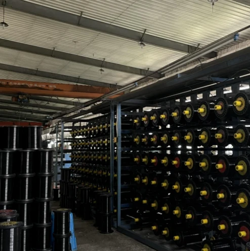
At Hangzhou Weiwo Geosynthetic Materials Co., Ltd., the production process starts from geotextile material selection and continues through manufacturing, inspection and export.
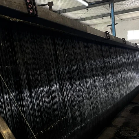
The fabric is selected according to the required mechanical and filtration characteristics. The yarn should have consistent physical condition without obvious damage that could affect the finished tube.
Weiwo uses different polypropylene yarn structures for geotextile tube production, including:
PP flat yarn
PP round yarn
PP open-mesh yarn
PP folded yarn
Different yarn structures can be selected according to the required fabric structure and project application.
The geotextile tube is then specially sewn and formed.
| Manufacturing Parameter | Common Industry Reference |
|---|---|
| Base polymer | Polypropylene (PP) |
| Fabric type | Woven geotextile |
| Fabric mass | Selected according to tube diameter, filling load and application |
| Tensile strength | Commonly several tens to more than 100 kN/m, depending on fabric grade |
| Seam strength | Designed according to tube size, filling pressure and required safety factor |
| Tube diameter | Customized according to project |
| Tube length | Customized according to drainage area and filling volume |
| Tube width | Fabric panels can be joined to achieve the required tube circumference |
| Sewing | Industrial geotextile sewing and seam reinforcement |
| Production arrangement | Multiple production lines/workshops according to order volume |
| Inspection items | Fabric weight, tensile properties, seam condition, dimensional inspection and visual inspection |
The tube length is not restricted to one fixed standard. For large projects, the width can also be joined according to actual site and installation requirements.
This is important for projects where the drainage area, filling volume or installation layout does not match a standard commercial tube size.
Production to Export Process
For overseas projects, the product is controlled through the production and export process.
Production → Booking → Loading → Customs Declaration → Export
|
Stage |
Typical Work |
|---|---|
| 01 Production | Material preparation, fabric processing, sewing and tube forming |
| 02 Booking | Arrange shipping space according to cargo volume and destination |
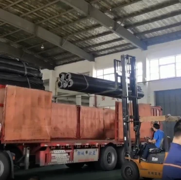
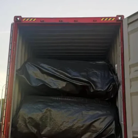
| 03 Loading | Pack and load finished geotextile tubes |
| 04 Customs Declaration | Prepare export documents and complete customs procedures |
| 05 Export | Arrange international shipment to destination port |
Weiwo's geotextile tubes have been shipped to countries including Mexico, Canada, Uruguay, Singapore and Malaysia, among other overseas markets.
Why Geotextile Tubes Are Used in Sludge Dewatering
Traditional sludge treatment can require large areas, mechanical equipment, buildings and continuous power consumption.
A geotextile dewatering system uses a different approach.
The sludge is conditioned, pumped into the tube and separated through the geotextile filtration structure. The main drainage stage relies on hydraulic pressure and gravity rather than a mechanical press or centrifuge.
|
Characteristic |
Typical Engineering Description |
|---|---|
| Equipment requirement | No mechanical press or centrifuge is required for the main gravity drainage stage |
| Power requirement | Pumps and polymer dosing require power; gravity drainage itself does not |
| Operator requirement | Filling, polymer dosing and site monitoring can be managed with a limited operating team |
| Tube dimensions | Diameter and length can be customized |
| Capacity adjustment | Number of tubes can be increased or reduced according to sludge volume and site area |
| Site arrangement | Tubes can be arranged in parallel or in filling cycles |
| Storage/stacking | Consolidated tubes can be arranged or stacked where permitted by the engineering design |
| Noise during drainage | Gravity drainage produces little mechanical noise |
| Volume reduction | More than 90% reduction may be achievable under suitable conditions |
| Project scale | Suitable for small, medium and large sludge dewatering projects |
Geotextile Tube Capacity Can Be Scaled
One practical advantage of the system is that treatment capacity does not have to depend on a single fixed mechanical machine.
If more sludge needs to be treated, additional tubes can be installed.
The basic relationship is:
Required treatment capacity → Pump flow → Filling schedule → Number of tubes → Available drainage area
For example, a project can be arranged with several tubes operating sequentially or simultaneously, depending on the available land, pump capacity and sludge production rate.
| Parameter | Common Industry Reference |
|---|---|
| Sludge flow rate | Approximately 50–500 m³/h per filling line for many projects |
| Solids concentration | Often below 5% for dilute dredged slurry; higher concentrations are common in conditioned sludge |
| Tube diameter | Approximately 2–30 m depending on project scale |
| Tube length | Commonly 20–100+ m for large projects, subject to site layout |
| Filling cycles | Determined by sludge production and tube drainage rate |
| Number of tubes | Calculated from total volume, tube capacity and project schedule |
| Drainage area | Normally designed with working space around each tube |
| Polymer dosage | Determined by laboratory/field jar testing rather than a universal dosage |
| Pump flow | Selected according to tube size, filling pressure and available equipment |
| Filling pressure | Controlled according to tube design and site conditions |
Reference Volume Reduction
One of the main purposes of dewatering is to reduce the amount of water that must be handled during subsequent treatment.
Under suitable sludge characteristics and operating conditions, the dewatered material can achieve a reference volume reduction of more than 90% within approximately one month.
This should be treated as a project reference rather than a universal value.
Actual volume reduction depends on:
- Initial water content
- Initial solids concentration
- Organic content
- Particle size
- Sludge type
- Polymer selection
- Polymer dosage
- Filling rate
- Tube dimensions
- Drainage conditions
- Weather and evaporation
- Required final solids concentration
| Indicator | Common Engineering Reference |
|---|---|
| Initial sludge water content | Often very high for dredged slurry |
| Initial solids concentration | Frequently 1–5% for dilute dredging slurry; project-specific |
| Solid retention | >99% under suitable conditions |
| Volume reduction | >90% can be achieved in suitable applications |
| Primary drainage | Often occurs within the first days after filling |
| Consolidation | Continues for weeks or longer |
| Final solids condition | Determined by project requirements and final disposal/reuse route |
Environmental Applications
The use of geotextile tubes has expanded as dredging, wastewater treatment, coastal engineering and environmental restoration projects require methods for handling water-rich materials.
In river, lake, reservoir, harbor and coastal projects, large quantities of sediment may need to be removed from the water and dewatered before further treatment or reuse.
Geotextile tubes can be used for:
Cofferdam filling
Land reclamation
Riverbank reinforcement
Dredged sediment dewatering
Rapid sludge dewatering and consolidation
Breakwater construction
Seawall-related applications
Coastal protection
River and lake sediment treatment
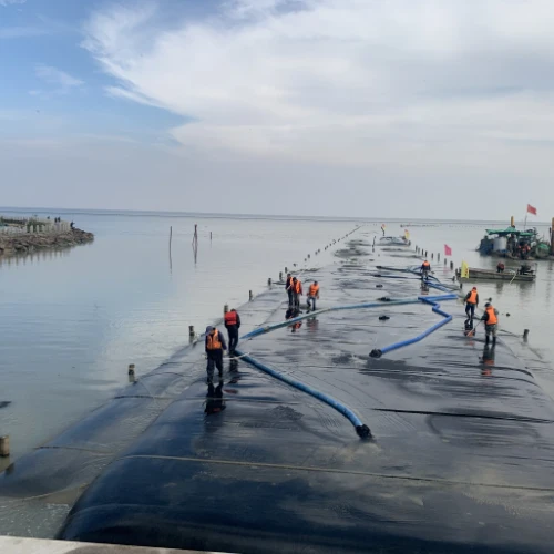
For coastal protection applications, high-strength synthetic fabric can be manufactured into tubes with different diameters and lengths. Depending on the engineering design, the tube may be filled with sand, mortar or another specified material and used as part of a breakwater, seawall or containment structure.
For river and lake sediment treatment, the process focuses on separating water from the sediment, consolidating the retained solids and determining whether the treated material can be reused.
Main Application Areas
River, Lake, Reservoir and Harbor Dredging
Geotextile tubes can be used to dewater contaminated or high-water-content bottom sediment removed from:
Rivers
Lakes
Reservoirs
Harbors
Ports
Docks
Coastal areas
Typical process:
Dredging → Pumping → Polymer Conditioning → Flocculation → Tube Filling → Filtration → Filtrate Collection → Gravity Drainage → Consolidation → Final Treatment
Municipal Sludge
Municipal applications include sludge generated by:
Water treatment plants
Wastewater treatment plants
Municipal sludge treatment facilities
The sludge is conditioned and pumped into the tube. The geotextile retains the solid fraction while water is discharged through the filtration structure and collected for further management.
Industrial Sludge
The technology can be applied to sludge from industries such as:
Chemical production
Pharmaceutical production
Textile and dyeing
Industrial wastewater treatment
For industrial sludge, chemical composition and contaminant concentration should be tested before selecting the treatment method.
Particular attention should be given to:
Heavy metals
Organic pollutants
pH
Suspended solids
Chemical compatibility
Final disposal requirements
Agriculture, Livestock and Aquaculture
Applications include:
Livestock farm wastewater
Manure-containing wash water
Agricultural wastewater
Plantation wastewater
Aquaculture waste
Aquaculture bed waste
The suitability of the final dewatered material for agricultural reuse depends on contaminant testing and local regulatory requirements.
Power, Steel, Aluminum and Ceramic Industries
Potential applications include:
Fly ash and bottom ash-related slurry treatment
Steel plant desulfurization sludge
Dust-removal sludge
Aluminum plant sludge
Ceramic plant sludge
The material characteristics of each industrial stream are different, so fabric selection and polymer conditioning should be based on actual samples.
Mining and Mineral Processing
Mining applications include:
Mine wastewater treatment
Ore washing wastewater
Mineral processing slurry
Waste recovery
Solid-liquid separation
Construction slurry dewatering
The system can separate water from slurry and retain the solid fraction for further recovery, storage or disposal.
Typical Engineering Workflows
| Application | Typical Process |
|---|---|
| River/lake dredging | Dredger → Pump → Polymer dosing → Flocculation → Tube filling → Filtration → Filtrate collection → Gravity drainage → Consolidation |
| Municipal sludge | Sludge collection → Conditioning → Pumping → Tube filling → Filtration → Drainage → Consolidation → Final handling |
| Industrial sludge | Sampling/testing → Polymer selection → Conditioning → Pumping → Filtration → Filtrate treatment → Consolidation → Disposal/reuse |
| Mining slurry | Slurry collection → Conditioning → Pumping → Tube filling → Filtration → Water recovery → Solid consolidation → Recovery/disposal |
| Coastal protection | Sand/mortar/slurry filling → Tube placement → Filling control → Shape formation → Breakwater/seawall/cofferdam application |
Geotextile Tube vs. Traditional Dewatering Methods
There are several ways to remove water from dredged sediment and sludge. The selection depends on project conditions rather than one method being suitable for every site.
| Method | Main Process | Common Engineering Characteristics | Main Limitations |
|---|---|---|---|
| Natural drying / disposal yard | Sludge placed in drying or disposal area | Simple process, low mechanical equipment requirement | Large land requirement, slow drainage and weather dependence |
| Mechanical dewatering | Filter press, centrifuge or other mechanical equipment | Controlled mechanical separation and relatively fast processing | Equipment investment, power consumption, workshop/building requirement |
| Geotextile tube | Polymer conditioning + pumping + geotextile filtration + gravity drainage | Flexible dimensions, scalable tube quantity, low mechanical requirement during drainage | Requires drainage area, filtrate collection and correct fabric/material selection |
Natural drying is technically simple and has been used for dredged sediment treatment.
However, large disposal yards may be required.
Because the sludge is exposed in the disposal area, uncontrolled return water or rainwater can create environmental management problems. If the return water is not properly collected and treated, it may affect surrounding water bodies.
Mechanical methods such as filter presses and centrifuges can provide controlled dewatering.
However, they generally require:
Mechanical equipment
Electrical power
Equipment investment
Buildings or workshops
Maintenance
Skilled operation
Fixed processing capacity
For large river or reservoir dredging projects where substantial quantities of sediment must be treated within a relatively short site schedule, equipment capacity and installation requirements become important design factors.
Geotextile tube systems move the main separation mechanism from mechanical pressing to:
Polymer conditioning + Hydraulic filling + Geotextile filtration + Gravity drainage
The system can be expanded by installing additional tubes, while tube dimensions can be adjusted according to the project.
The drainage area, filtrate management and final solids handling still need to be designed as part of the complete system.
Project Parameters Required Before Selecting a Dewatering Filter Bag
A dewatering tube should not be selected from sludge volume alone.
For engineering selection, the following information is normally required:
| Project Parameter | Common Engineering Reference / Unit |
|---|---|
| Sludge type | Dredged sediment / municipal / industrial / mining |
| Total volume | m³ or tons |
| Daily production | m³/day or tons/day |
| Solids concentration | % dry solids |
| Water content | % |
| Particle size | mm / particle-size distribution |
| pH | pH value |
| Chemical composition | Laboratory analysis |
| Heavy metals | mg/L or mg/kg, depending on sample type |
| Organic contaminants | mg/L or mg/kg, where applicable |
| Polymer/flocculant | Type + dosage from testing |
| Pump capacity | m³/h |
| Pipeline diameter | Commonly approximately 75–300 mm, project-specific |
| Available drainage area | m² |
| Required tube diameter | Approximately 2–30 m, project-specific |
| Required tube length | Commonly 20–100+ m for large projects |
| Number of tubes | Calculated according to volume and schedule |
| Filtrate treatment | Collection / treatment / discharge / reuse |
| Final solids destination | Reuse / reclamation / construction / disposal |
| Destination country | Required for export and logistics |
These parameters allow the manufacturer to determine the appropriate geotextile structure, tube dimensions, quantity and production arrangement.
How to Determine the Tube Size
Tube size should be considered together with sludge volume, solids concentration and site conditions.
A simplified engineering workflow is:
1. Determine sludge volume
↓
2. Test solids concentration and particle characteristics
↓
3. Conduct polymer/flocculation testing
↓
4. Determine required filtration performance
↓
5. Select geotextile structure and fabric
↓
6. Determine tube diameter and length
↓
7. Calculate the required number of tubes
↓
8. Check drainage area and filling schedule
↓
9. Design filtrate collection
↓
10. Confirm final solids handling
This approach is more useful than selecting a standard tube size first and trying to adapt the project around it.
Filling and Installation Considerations
The tube is filled through a pipeline connected to a pump.
During filling, the operator needs to control the filling rate and monitor the shape and condition of the tube.
Important factors include:
Pump flow
Filling pressure
Polymer dosage
Floc formation
Sludge concentration
Tube dimensions
Seam configuration
Ground condition
Drainage direction
Filtrate collection
Distance between adjacent tubes
The tube should be installed on a prepared drainage area suitable for the expected load and project conditions.
For large-scale projects, the installation layout should allow equipment access, pipeline routing, inspection and subsequent removal or reuse of the consolidated material.
What Happens After Dewatering?
Dewatering is not the final step of the project.
After sufficient drainage and consolidation, the project must determine what to do with the retained solids.
Possible routes include:
Riverbank Protection
Suitable treated material may be incorporated into riverbank protection works where permitted by the project design.
Landscaping
Uncontaminated inland sediment can potentially be used as landscaping soil after appropriate testing.
Land Reclamation
Dewatered material may be considered for reclamation or earthwork applications where its engineering properties meet the requirements.
Organic Soil Applications
Where the material is confirmed to be suitable and free from relevant contamination, treated sediment may be considered for soil improvement or organic planting applications subject to local requirements.
Disposal
Material containing heavy metals or other contaminants may require controlled disposal instead of direct reuse.
The final route should always be based on laboratory testing, project specifications and applicable environmental regulations.
What We Can Provide for Your Dewatering Project
As a geotextile dewatering bag manufacturer, we can produce the bags according to the material being treated, project scale and installation requirements.
For an overseas project, our service can cover the main stages from product selection to shipment.
| Your Project Requirement | What We Can Provide |
|---|---|
| Dredged sediment or sludge dewatering | Geotextile tube selection based on material characteristics |
| Different sludge volumes | Tube quantity and size recommendations based on project volume |
| Different drainage areas | Customized tube diameter and length |
| Large-volume orders | Production arrangement through multiple workshops |
| Special fabric requirements | PP yarn and woven geotextile configuration according to application |
| Different filling methods | Tube configuration according to pump and filling conditions |
| Coastal or marine projects | Tubes for sand, mortar or specified filling materials |
| Overseas projects | Production, packing, loading and export arrangement |
| Repeat or bulk orders | Production scheduling according to required quantity and delivery time |
The geotextile tube is manufactured according to the actual application rather than using one fixed specification for every project.
For quotation, you can send us the material type, approximate treatment volume, application and destination country. If you have drawings, test reports, required dimensions or existing project specifications, we can review them together.