
Geotextile Dewatering Bags: Construction Method for Sludge Dewatering
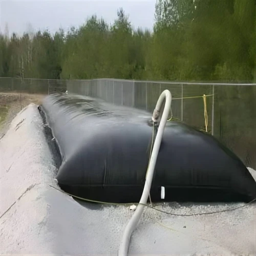
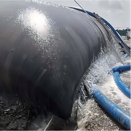
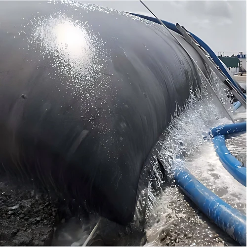
Geotextile dewatering bags are used to separate water from dredged sludge by combining polymer flocculation with geotextile filtration. During operation, the dredged slurry is mixed with PAM and pumped into the tube. Water passes through the geotextile fabric, while the concentrated sludge remains inside the tube.
For a large dredging project, the result is affected by more than the tube itself. The dewatering area, drainage layer, polymer dosage, filling pressure, tube arrangement and filling sequence all need to be considered before construction.
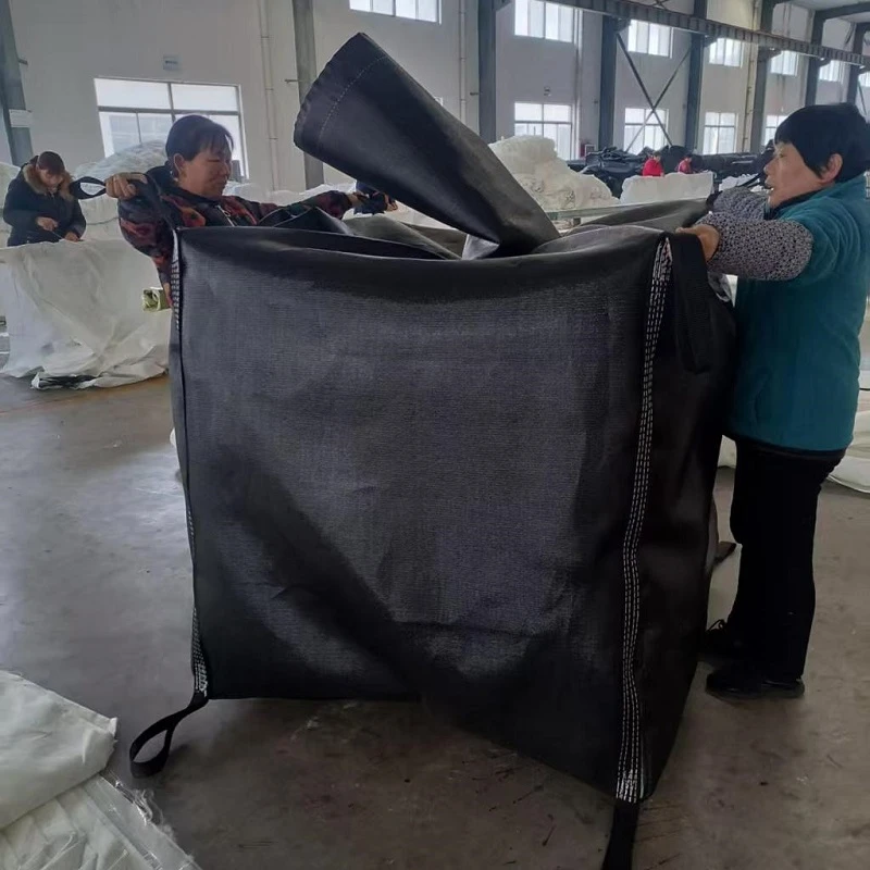
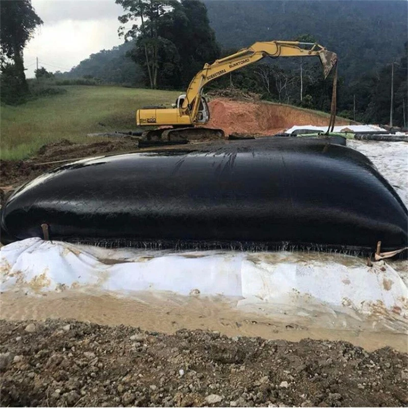
Geotextile Dewatering Bag Design
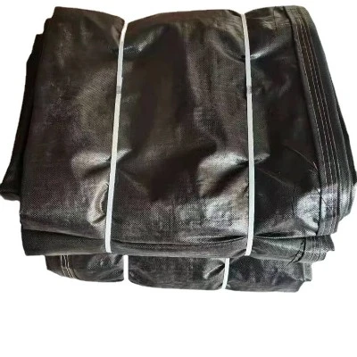
The circumference of a geotextile tube is commonly designed between 8 and 30 m. The length can be adjusted according to the available site and the amount of sludge, with 30–60 m being a common range.
A tube should not simply be made as long as possible. When the tube is too long, it becomes difficult to keep it straight during filling. Once the tube moves or swings, its effective filling volume decreases and more site space may be occupied.
A larger tube can hold more sludge, but it also normally takes longer to dewater.
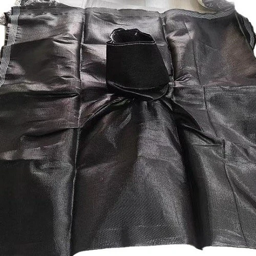
Filling ports are commonly 0.2–0.4 m in diameter, with a sleeve length of about 0.5–1.0 m. One filling port can normally be arranged every 10–15 m.
The number of filling ports needs to match the tube size. Too many ports can weaken the tube, while too few ports can make the filling uneven and cause the tube to deform during operation.
Preparing the Dewatering Area
Before the geotextile tubes are installed, the dewatering area needs to be leveled and compacted.
The purpose of the area is not only to support the filled tubes. It also needs to collect and discharge the filtrate released during dewatering.
For a 10,000 m² dewatering area, the drainage system can include an impermeable liner, filtration layer, perforated drainage pipes, drainage channels, a collection sump and pumps.
A typical liner structure consists of:
200 g/m² needle-punched nonwoven geotextile
2 mm HDPE geomembrane
200 g/m² needle-punched nonwoven geotextile
The liner is installed over the compacted clay or prepared subgrade.
A drainage layer of approximately 5 cm graded gravel can then be placed above the liner. Perforated drainage pipes are installed within this layer to collect the water passing through the geotextile tubes.
The collected water flows into the drainage channels and then into the collection sump for sedimentation or further treatment before discharge.
Taking all factors into account, the geotextile tubes for this project will be stacked in two layers after filling; the dimensions and quantities are as follows:
| Product Name | Specification | Tubular bag dimensions (circumference × length) | Quantity (items) |
| High-strength geotextile tube | WEIWO | 15.7m*30.6m | 40 |
| High-strength geotextile tube | WEIWO | 15.7m*28.8m | 40 |
Note:
1. Three filling sleeves are evenly spaced along the length of the tube; each sleeve is 0.6 m long and 0.3 m in diameter.
2. The seams joining the tube fabric are stitched with six rows of thread.
The supporting surface under the tubes needs special attention.
The impermeable layer below the drainage system can have a slope toward the drainage channel so that water can leave the area.
However, the upper surface supporting the geotextile tubes should remain level. If the surface is sloped too much, the tube can move or roll when it is being filled.
Another arrangement is to form a small slope from both sides toward the center. In this case, the first tube is filled at the center and the following tubes are filled toward both sides.
This arrangement allows the tubes to move slightly toward the center during filling and helps reduce gaps between adjacent tubes.
Access paths should also be left around the dewatering area. A passage about 1.0 m wide is generally sufficient for workers to operate valves, inspect the tubes and carry out repairs.
Quality and Technical Requirements for Geotextile Tubes
| No. | Experimental Projects | Unit | Reference Standards | Nominal value | |
| 1 | Tensile strength | Longitudinal | kN/m | SL235-2012 | ≥70 |
| Horizontal | kN/m | SL235-2012 | ≥90 | ||
| 2 | Elongation at break | Longitudinal | % | SL235-2012 | ≤20 |
| Horizontal | % | SL235-2012 | ≤25 | ||
| 3 | Permeability | 1/m²/s | ISO 11058 | ≥20 | |
| 4 | Equivalent pore size (O90) | mm | GB/T14799-2005 | 0.2~0.6 | |
| 5 | UV resistance (strength retention after 500 hours) | % | ASTM D4355 | ≥90 | |
| 6 | Seam tensile strength | kN/m | ISO 10321 | ≥60 | |
| 7 | CBR puncture strength | kN | ISO 12236 | ≥8.0 | |
| 8 | Abrasion resistance (strength retention) | % | ASTM D4886 | ≥70 | |
| 9 | Dynamic cone drop test (puncture diameter) | mm | ISO 13433 | ≤13 | |
| 10 | Maximum fill height | m | ≥2.5 | ||
Preparing and Adding PAM
PAM, or polyacrylamide, is commonly used to condition the dredged slurry before it enters the geotextile tube.
The type of PAM depends on the sludge. Anionic PAM and cationic PAM are commonly used for different types of wastewater and sludge.
The polymer should not be selected only according to a general dosage table. The sludge from different rivers, lakes, industrial processes or dredging areas can behave very differently.
A small-scale flocculation test should be carried out before full-scale filling.
The dosing system can include two polymer tanks, a mixer and a dosing pump.
Water is first added to the preparation tank. The mixer is started before adding PAM.
A mixing speed of about 100–300 rpm can be used as a reference. PAM powder should be added slowly along the vortex instead of being poured into the tank all at once.
If too much dry PAM enters the water at one time, the powder can form lumps that are difficult to dissolve.
After the PAM has been added, mixing normally continues for more than 30 minutes.
An anionic PAM solution can be prepared at around 0.1% concentration as an initial reference. Cationic PAM can be prepared at approximately 0.1–0.5%, depending on the material being treated.
The prepared solution should not be stored for too long. Anionic PAM solution is generally used within about 36 hours, while cationic PAM solution should normally be used within 24 hours.
A dosage of around 1–2 ppm can be used as a starting reference for some applications, but the actual dosage needs to be determined from testing.
The operator should look at the floc size, settling behavior and filtrate clarity.
If the flocs are too small and the water remains cloudy, the dosage or mixing condition may need adjustment. If excessive polymer is used, the treatment cost increases without necessarily improving the dewatering result.
For this reason, the dosage should be adjusted during commissioning rather than fixed before the sludge is tested.
Laying Out the Geotextile Tubes
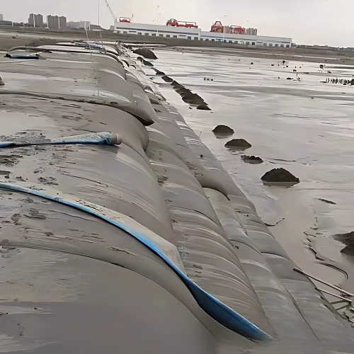
The tubes are placed according to the shape of the dewatering area.
Adjacent tubes should be positioned closely together. An overlap of approximately 30 cm can be used where required by the site arrangement.
There are two common layouts: sequential placement and staggered placement.
Staggered placement can provide good stability, but it takes more time to position and secure the tubes. For many projects, sequential placement is easier to operate.
When tubes are stacked in several layers, the upper tubes should normally be shorter than the lower tubes.
The first tube is particularly important.
If the first tube moves during filling, its position will affect every tube installed next to it. Before filling starts, the tube should therefore be fixed with non-stretching rope or another suitable restraint.
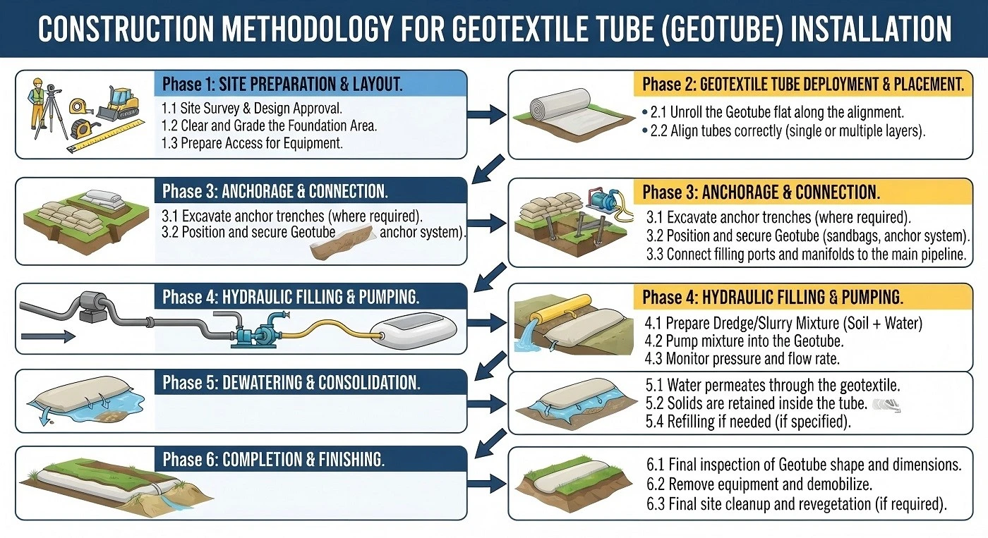
Dredging and Slurry Transfer
For underwater dredging, a cutter suction dredger can be used to remove sediment from the river or water body.
The dredged slurry is transported through a pipeline to the sludge collection system.
A two-stage tank arrangement can be used. The first tank receives the dredged slurry, while the second tank provides storage before treatment.
A screen can be installed between the two tanks to remove floating debris, stones and other large materials.
This step is important because large foreign materials can block the pump, valves or filling ports later in the process.
The treated slurry is then pumped toward the geotextile tubes.
Filling the Geotextile Tube
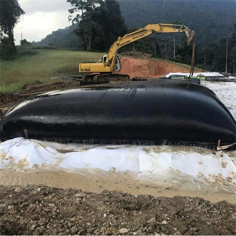
A slurry pump is used to transfer the conditioned sludge into the tube.
For example, a 22 kW pump unit can be used for a suitable project, but the actual pump should be selected according to the pumping distance, elevation difference, pipeline diameter and required flow rate.
The main pipeline is divided into branch pipes. Each branch pipe should have its own valve.
The filling pressure must be controlled according to the tube and pumping system. Around 0.05 MPa can be used as a reference for some applications, but the actual operating pressure should be confirmed during commissioning.
PAM can be injected into the slurry pipeline through a static mixer.
The polymer injection pressure needs to overcome the pressure in the sludge pipeline. A pressure difference of approximately 0.01–0.02 MPa can be used as a reference for the dosing point.
During filling, workers should monitor the tube continuously.
The tube height, tube shape, valve position and surface condition should be checked throughout the operation.
Once the tube reaches its maximum filling height, filling must be stopped.
A maximum filling height of about 2.3 m can be used as a project reference.
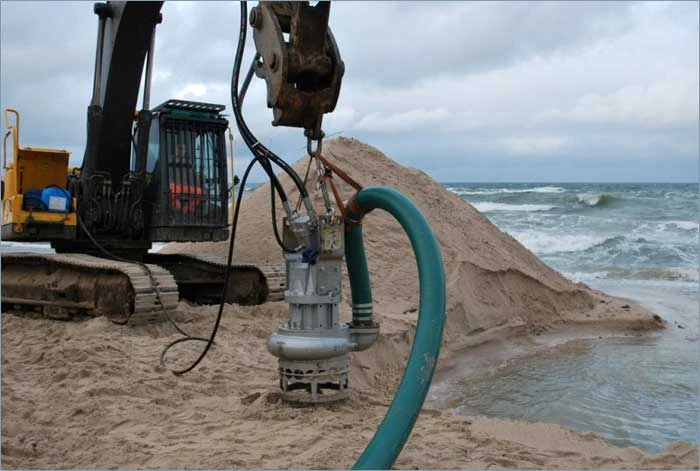
Why Filling Should Start From the Center
For a large dewatering area, filling the tubes from one side to the other can make tube positioning difficult.
Starting from the center gives the first tube a fixed reference position.
After the center tube is filled, the next tubes can be filled toward both sides.
This is particularly useful when the supporting drainage layer has a slight slope toward the center. The adjacent tubes can gradually move toward each other instead of leaving large gaps.
The objective is simple: keep the tubes stable, reduce unused space and prevent excessive movement during filling.
Single-Port and Multiple-Port Filling
A tube can be filled through one port or through several ports at the same time.
With single-port filling, the operator needs to close the valve, disconnect the branch pipe and move it to another filling port after one section has been filled.
There is a practical problem with this method.
After the valve is closed, the branch pipe can still contain a large amount of slurry and water. The pipe becomes heavy and difficult to move. Slurry may also leak during the connection change.
Multiple-port filling avoids much of this repeated pipe movement.
Several filling ports on the same tube are connected to separate branch pipes. The valves are then used to control the flow.
The valve operation becomes more complicated, but the slurry can enter different parts of the tube at the same time. This generally gives better control of the filling shape and reduces the need to repeatedly move slurry-filled pipes.
For projects where the pipe layout and valve system can be properly managed, multiple-port filling is a practical way to carry out continuous filling.
Controlling the Filling Cycle
A geotextile tube should not be filled continuously until it becomes completely full.
When the tube reaches the maximum filling height, pumping is stopped.
The tube is then allowed to release water and settle.
As the water leaves the tube, the sludge volume decreases and the tube height drops. The next filling cycle can then begin.
Depending on the sludge properties and the treatment requirements, approximately 7–8 filling cycles may be required.
The actual number should be determined from the behavior of the tube during construction rather than fixed only from theoretical calculations.
After filling, the filling sleeves should be tied with geotextile straps or rope.
Wire should not be used because it can cut or damage the geotextile.
If a damaged area is found, filling should be stopped and the area repaired immediately.
The stitching spacing should not exceed 5 mm.
Multi-Layer Tube Filling
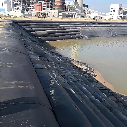
When the site area is limited, geotextile tubes can be stacked in multiple layers.
The lower tubes must first complete their required filling and dewatering stage.
The upper tube is then placed between two lower tubes.
This arrangement is important because the lower tubes provide support for the upper tube.
There will normally be a V-shaped gap between two lower tubes. When the upper tube is filled, part of the upper tube may sink into this gap.
This creates a local deformation and can increase pressure in that area.
A flexible filling material can be placed in the V-shaped gap before the upper tube is filled. The purpose is to provide a more even supporting surface.
The condition of the lower tubes must also be checked.
If the lower tubes are not evenly arranged, or if the sludge inside them has not dewatered sufficiently, the upper tube can deform during filling.
This can reduce the effective volume of the upper tube and create local stress on the geotextile.
For multi-layer systems, the lower tubes should therefore be checked for their shape, contact condition, stability and moisture content before the next layer is installed.
A final sludge moisture content of approximately 50% can be used as a reference for judging whether the dewatering stage has substantially progressed to the required condition.
Final Height and Sludge Volume
After the filling cycles are completed, the tube continues to lose water and settle.
The final dried height may be approximately 80% of the maximum filling height in some projects.
This value can be used for preliminary estimation of the final sludge volume.
For project calculations, however, the actual tube dimensions and measured settlement should be used instead of relying only on the 80% reference value.
Final Disposal
The disposal method depends on the final moisture content, sludge composition, environmental requirements and site conditions.
If the dewatered sludge can remain on site, the filled geotextile tubes may be covered with soil after reaching the required condition.
The filled tubes can remain as part of the stabilized fill structure.
If the sludge needs to be removed, the geotextile tube can be opened with construction equipment after dewatering.
The sludge and cut geotextile material can then be transported to an approved disposal or treatment facility.
What Needs to Be Checked Before Construction
A geotextile dewatering project should be checked from the beginning rather than waiting until the filling stage to solve problems.
Before construction, confirm:
- Sludge type and solids concentration
- Total sludge volume
- Required final moisture content
- Available dewatering area
- Tube circumference and length
- Number and position of filling ports
- PAM type and dosage
- Pump capacity and filling pressure
- Drainage and filtrate collection system
- Tube fixing method
- Filling sequence
- Multi-layer stacking requirements
- Final disposal method
The most important point is that the geotextile tube, polymer system, pumping system and drainage area need to be designed together.
A tube with suitable filtration properties can still perform poorly if the polymer dosage is wrong, the drainage layer is blocked, the filling pressure is not controlled, or the tube is placed on an unstable surface.
For this reason, field testing before full-scale filling is an important part of the construction process.